As a general rule, a cabinet can be described like a structure having two purposes: to be fitted with one or more loudspeakers, and to prevent loudspeakers rear radiation from mixing with direct radiation.
Speakers walls tend to be excited by both internal pressure and by the energy transmitted from the loudspeakers structure.
A list follows containing many design solutions, starting from classic and ending up with up-to-date techniques.
Sound absorbing and deadening
Nowadays many designers agree that absorbing materials cannot be useful in cabinet damping. Some even argue that absorbing is detrimental for transient response and efficiency. It can be useful to prevent the speakers’ rear radiation from bouncing back to them; however, that issue can be solved beforehand by studying internal cabinet geometry.
Much better are damping materials like hi-density PVC or sheet tar, provided they perfectly adhere to the wall. They are useful even if they don’t cover the entire wall. The best position is on the wall centre, covering at least one third of the wall.
Bracing
A classic of good cabinet design is bracing, which consists in dividing a wall into two sections by adding a strengthening element parallel to the longer side. In this way a higher fundamental resonant frequency is obtainable without varying panel dimensions.
It is possible to joint opposite cabinet sides so that they cannot vibrate according to internal pressure. This kind of stiffening is more efficient when used to connect two or more bracing mounted parallel to the longer side of the walls.
Such bracing can increase the resonant frequency by up to four times.
As a general rule, it can be said that high resonant frequency is desirable for three reasons:
1-Every musical track average energy is in reverse relation with frequency.
2-High frequency resonant mode in a cabinet wall requires that different wall sections vibrate in opposite directions. In this way is very hard to obtain high sound pressure inside a cabinet. Outside there will be not much sound propagation due to cancellations and reduced moving areas.
3-Due to the reduced moving areas, a wall excited by high frequencies will tend to radiate perpendicularly to its surface. This is desirable for every cabinet wall except for the one facing the listening position, as the output energy will not overlap with the direct sound.
Walls’ shape
Resonant frequency isn’t independent of the cabinet walls’ shape. Thickness and area being equal, a long and narrow wall will present a much higher resonant frequency than a square wall. Theoretically speaking, resonant frequency is equal to the reciprocal of the square root of the shorter dimension; whenever high accuracy is necessary, experimemtation is essential.
Another rule to raise resonant frequency in a structure is to employ high stiffness to weight ratio, keeping in mind that good damping requires a certain amount of mass.
Materials mixing
Different materials are characterized by different resonant frequencies due to their specific gravity, their fibre, or composition: they tend to react in different ways to mechanical stress. Those differences can be used to evaluate the best choice for a given project.
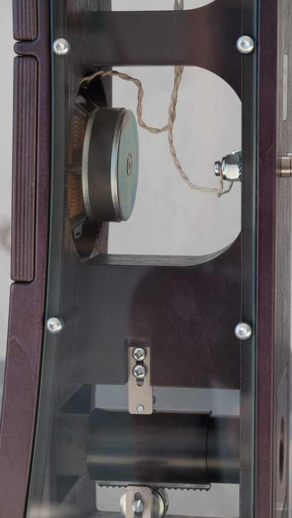
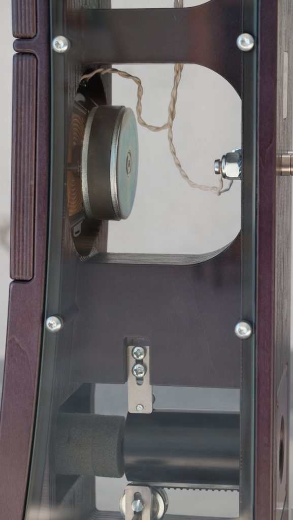
The best way to take advantage of those differences is by mixing different materials. This can be accomplished not only by coupling different layers, but also by assembling a cabinet using a different material for each wall. For this reason, Atomica speakers’ cabinets are built using up to four different materials. For example Floor and Book 2 speakers are made from two different types of solid plywood, tempered glass, and AISI 304 stainless steel. They work together as an extremely inert structure, which is free of every kind of interference. This kind of structure remains inert also at high listening levels, not only because of their excellent materials quality, but also because those materials present such different mechanical and resonance parameters that they reciprocally repress resonant forces.
Walls’ curvature
Resonant frequency depends on walls’ curvature. Up-to-date machining processes make possible to build curved surfaces, made of wood or other materials, giving the opportunity to enormously increase the stiffness and therefore the resonant frequency of a cabinet. Atomica speakers are made using the best numerical control machines, making it possible to obtain every kind of shape, creating loudspeakers that are structurally unrivalled and at the same tim
e incredibly pleasing to the eye.
The use of curved shapes can be taken to its extreme by making a spherical cabinet. We have achieved this goal with the Atomica Giove speakers, using a specific proprietary milling program that allows the creation of a perfect sphere made of very hard solid wood.
Materials’ direction
There are materials characterized by a directional structure, or by a fibre (natural wood). Those materials can be glued or fixed togetrer to form a multi-layer panel. This method is the one used by plywood manufacturer. For instance, the most common type of 30 millimetre-thick okoumè plywood consists of twelve layers, which are alternately oriented, glued and pressed. Thanks to torsional and bending compensation, this process allows to have at least four times better characteristics than single layer okoumè wood.
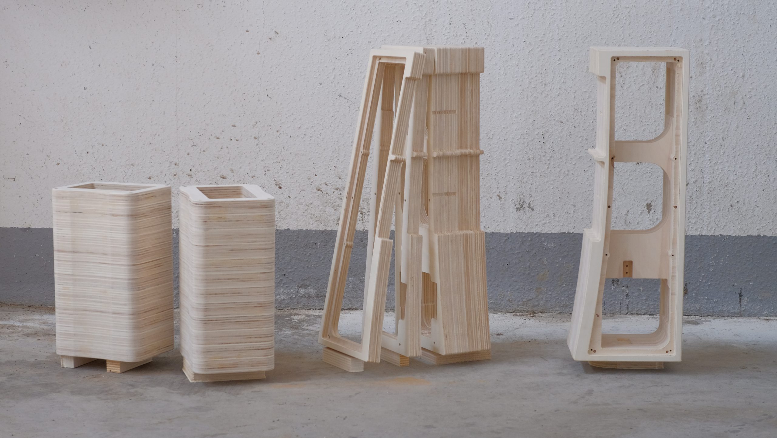
Atomica Floor, Book 2 and Bookshelf XL speakers employ an extreme concept of fibre oriented compensation. Their cabinet are made using multiple layers of plywood, glued and pressed using hydraulic press at several tons of pressure. We obtain a very special cabinet, whose wooden part consists of dozens of alternately oriented wooden layers. Layer structures also makes it possible to totally incorporate bracing, with shapes and efficiency not even remotely imaginable with conventional methods.
Gluing, fitting and screwing
Whatever the procedure to assemble the parts of a cabinet is, i.e., by gluing, fitting, and/or screwing together, an experienced manufacturer will be faced with a doubt: will I get a pair of cabinets with similar mechanical characteristics? Given the importance of equality between two loudspeakers required by stereophony, it is normal for a conscious designer to have an eye on how the cabinet parts are assembled. This phase can create stereophonic dissimilarity far more severe than those usually avoided by, for example, selecting and matching the components of a crossover.
In Atomica speakers the problem is tackled thanks to innovative machinery and techniques, never before used in the audio world.
For instance, the parts of a cabinet – whether made of wood, glass, or metal – are selected and milled by numerical control as well as any screw, bolt, or bonding dowels. At this point the frames are coupled and glued together in the same press, at the same pressure, and for an equivalent time. All clamping components are screwed with very precise dynamometric tools. This results in cabinet sets whose accuracy is excellent to say the least.
REFERENCES
- Ahnert W, Steffen F, “Sound Reinforcement Engineering”, 1999.
- Bailey AR, “Non-resonant Loudspeakers Enclosure”, 1965.
- Benson JE, “Theory and Design of Loudspeaker Enclosures”, 1972.
- Olson HF, “Direct Radiator Loudspeaker Enclosures”, 1972.
- Small RH, “Closed-Box Loudspeaker Systems”, 1972.
- Small RH, “Direct-radiator Loudspeaker System Analysis”, 1972.
- Zwikker C, Kosten CW, “Sound Absorbing Materials”, 1992.